Key Use Cases
Tools in Detail
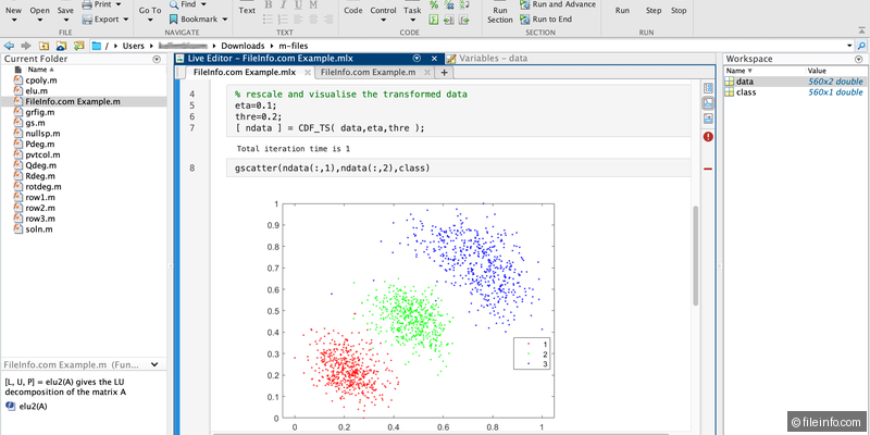
MATLAB
The foundational computing environment for automotive algorithm development. Provides matrix operations, signal processing, optimization, and data analysis used throughout the development workflow.
Simulink
Graphical block diagram environment for modeling dynamic systems. The standard for designing automotive control algorithms (powertrain, chassis, ADAS) with continuous and discrete-time simulation.
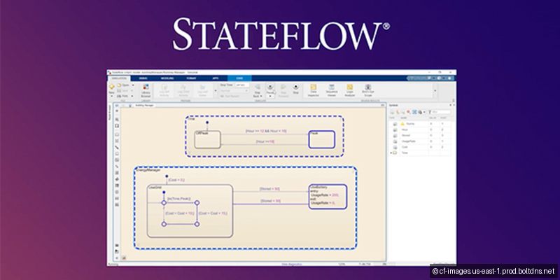
Stateflow
State machine and flow chart design tool integrated with Simulink. Used for modeling supervisory logic, mode management, and diagnostic state machines in ECU software.
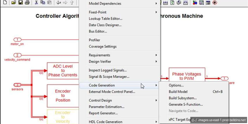
Embedded Coder
MathWorks' production code generator. Generates MISRA-C compliant, optimized C/C++ code from Simulink models with ISO 26262 qualification kit for safety-critical applications.
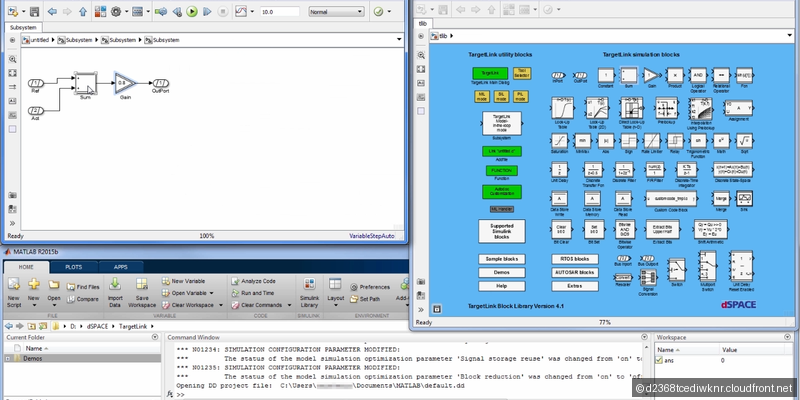
dSPACE TargetLink
Production code generator competing with Embedded Coder. Known for generating highly optimized, memory-efficient code with comprehensive back-to-back testing support.
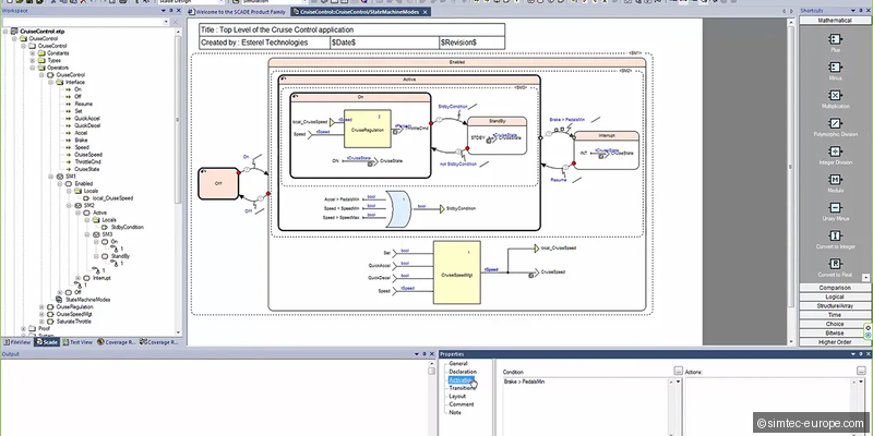
SCADE Suite (Ansys)
Model-based development environment for safety-critical embedded software. KCG code generator is qualified to DO-178C DAL A and ISO 26262 ASIL D for aerospace and automotive.
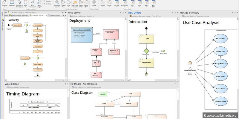
Enterprise Architect
UML/SysML modeling tool for system architecture design. Used in automotive for requirements engineering, system decomposition, and software architecture documentation.
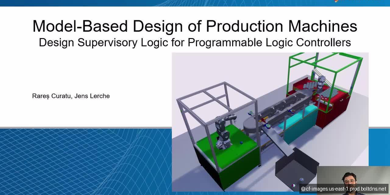
Industry Context
Model-based development has fundamentally transformed automotive software engineering. Instead of writing thousands of lines of C manually, engineers design algorithms graphically in Simulink, validate through simulation, and generate production code automatically. This catches errors earlier, ensures consistency between design and implementation, and provides ISO 26262 traceability. MATLAB/Simulink dominates with ~90% market share. The tooling investment is substantial but productivity gains are proven across thousands of production programs.
Typical Workflow
The MBD workflow follows the V-model: system requirements (SysML) → control algorithm design in Simulink/Stateflow → MIL validation against plant models → code generation (Embedded Coder/TargetLink) → SIL back-to-back testing → PIL verification on target MCU instruction set → AUTOSAR integration → HIL validation. Traceability links connect requirements → model elements → generated code → test results throughout.
Selection Guide
Pro Tips
Use Simulink data dictionaries from the start - retrofitting variable scoping into large models is painful.
Design for code generation from day one: use fixed-step solvers, define data types explicitly.
Run MIL vs SIL back-to-back tests with every code generation to catch numerical differences early.
Use Simulink's Fixed-Point Tool to profile dynamic range before setting data types manually.
Structure large models using Model Reference (not library blocks) for incremental code generation.